RTK-GPS at Rover
After the base station was operational, I started to do some tests on the ROSMower. In terms of RTK-GPS, the moving object gets named as Rover, so I name my Mower also Rover in this topic.
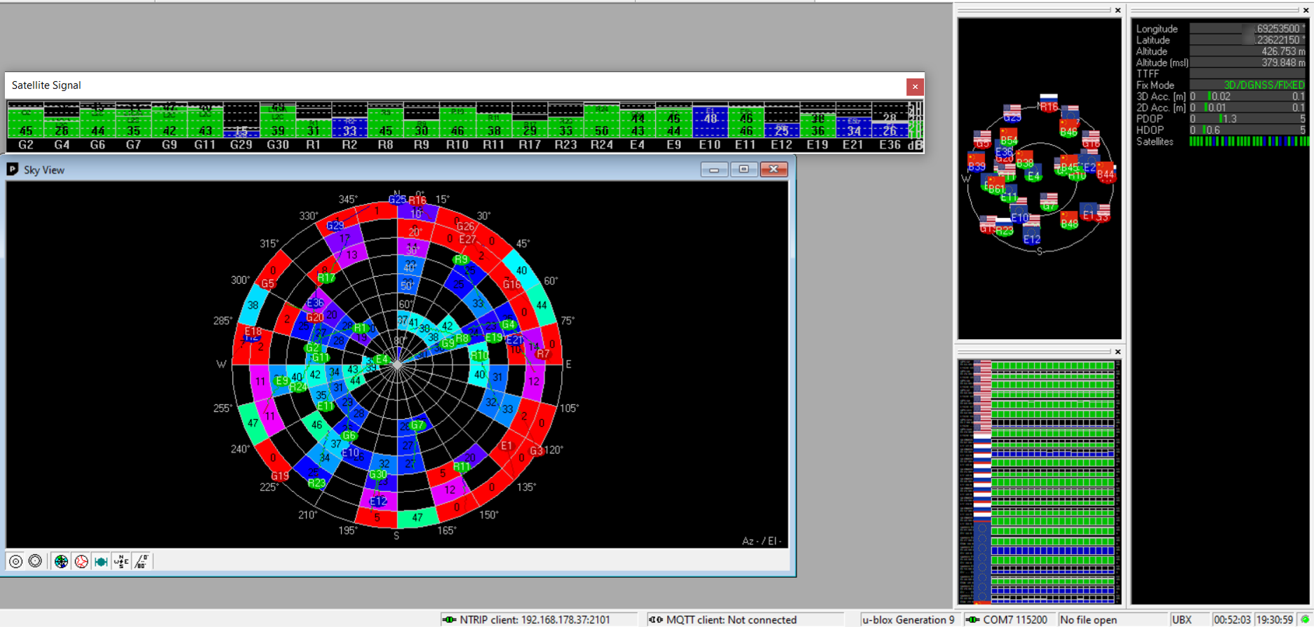
To get cm-level accuracy, the GPS receiver needs a state called FIXED. To do so, you need a base station feeding correction data to the Rover. Also the Rover itself must have good satellite signal. You want to see many satellites with approx 40dB covering the entire sky. Under perfect condition, you get a FIX with ease but in real world, there are many issues like trees, buildings or other objects, which either block GPS signal or causes reflection. The receiver will also catch the reflection, which is called multi-path. The receiver does some mathematical calculation and the result is either a FIX or a FLOAT. In case of FLOAT, we have a good precision of approx. 20 cm, but this is not ok for the purpose of mowing by lanes.
I had some hard time to get a FIX on the Rover and I’m still fighting with antenna setup. To solve this issue, I started some tests to determine best antenna setup for my conditions.
Test field
You find many example test setup on the internet bust most of them are under best condition meaning you have either lot of open space around the antenna or it is placed on a high building. But in reality, the Rover will act close to the ground and there are many objects which influence the signal.
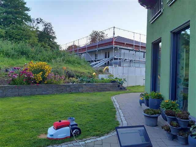
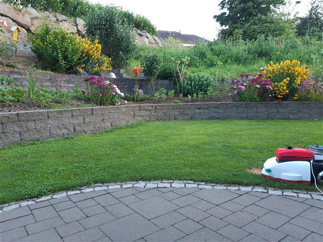
I’m living in a village with lots of small houses. The area of each ground is between 500-600m² which means, the houses of the neighbours are only a couple of meters beneath my own. The rover has to operate between houses. Moreover, there are many hills which means, the houses of my neighbours are often higher than my own.
Test conditions
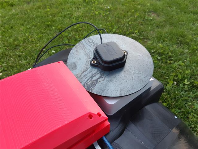
During the test, the Rover is placed approx 2.5 meters beneath the house at a static position. To keep things easy, the Rover itself is turned off, so there is no electronical noise from NVidia Jetson, Wifi or other components. During each test, the antenna gets placed on the same position on the Rover. The simpleRTK board is placed approx 10cm beneath the antenna (under the red cover) and connected to a Notebook, which is approx 2m beneath the Rover.
During each test, I measuse the time between cold-start of the GPS module and the first RTK-FIX solution.
Test objects
The purpose of this test was to find best antenna setup. As we already know, a ground plane should be added to antenna to get good signal. But which kind of material is a good solution? How affect size and material the signal? Expensive GPS antennas are often constructed as choke ring antennas. They’re commonly used for fixed installation like base stations but I didn’t find examples where they’re used for Rover. As they’re expensive, I tried to build a poor man choke ring antenna.
The test objects are:
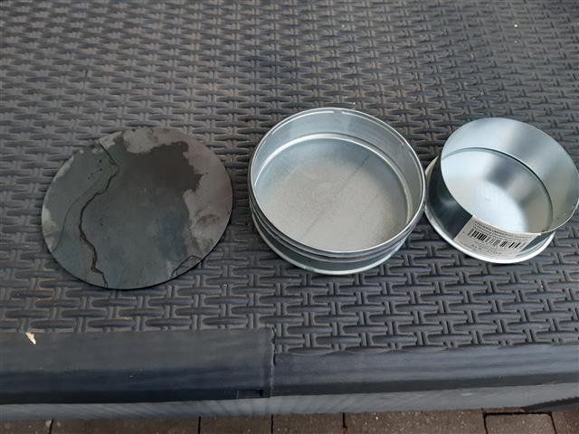
- steel disk 170mm x 3mm
- round steel box with diameter 120mm and 60mm height (cover for stove pipes from local hardware store). I name it small box in further.
- round steel box with diameter 150mm and 50mm height (cover for stove pipes from local hardware store). I name it large box in further.
- poor man choke ring antenna. Simply place the smaller box inside the larger one and place antenna inside
Result
After a first test run, I tried to reproduce the results for some tests with a 2nd test run. Sadly the results varies a lot. The time between 1st and 2nd test was approx 30 minutes. As it was late evening, temperature changes fast. This might influence the time to get a fix as the F9P module if sensitive to this.
To get a clear picture, I should re-run each single test multiple times and build the mean value but I got the feeling, that small box with antenna placed outside is a good candidate and I’ll go this way.
| Test | Time to Fix | Fix Mode | Lon | Lat | Alt | 3D acc | 2D acc | PDOP | HDOP | |
|---|---|---|---|---|---|---|---|---|---|---|
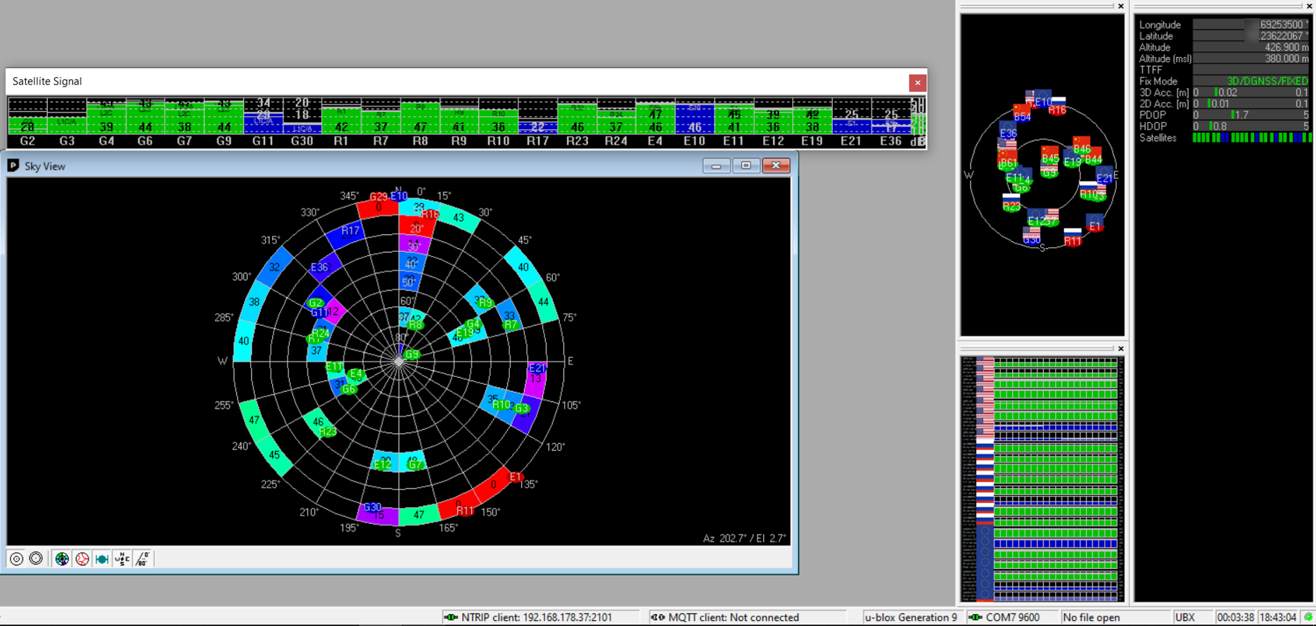
| Choke Ring | 02:35 | 3D/DGNSS/FIXED | X.69253500 | 5X.23622067 | 426,9 | 0,02 | 0,01 | 1,7 | 0,8 | |
| Choke Ring 2.test | 05:24 | 3D/FIXED | X.69253583 | 5X.23621983 | 426,89 | 0,02 | 0,01 | 1,3 | 0,6 | |
| steel plate | 02:43 | 3D/DGNSS/FIXED | X.69253567 | 5X.23622000 | 426,7 | 0,02 | 0,01 | 1,5 | 0,7 | |
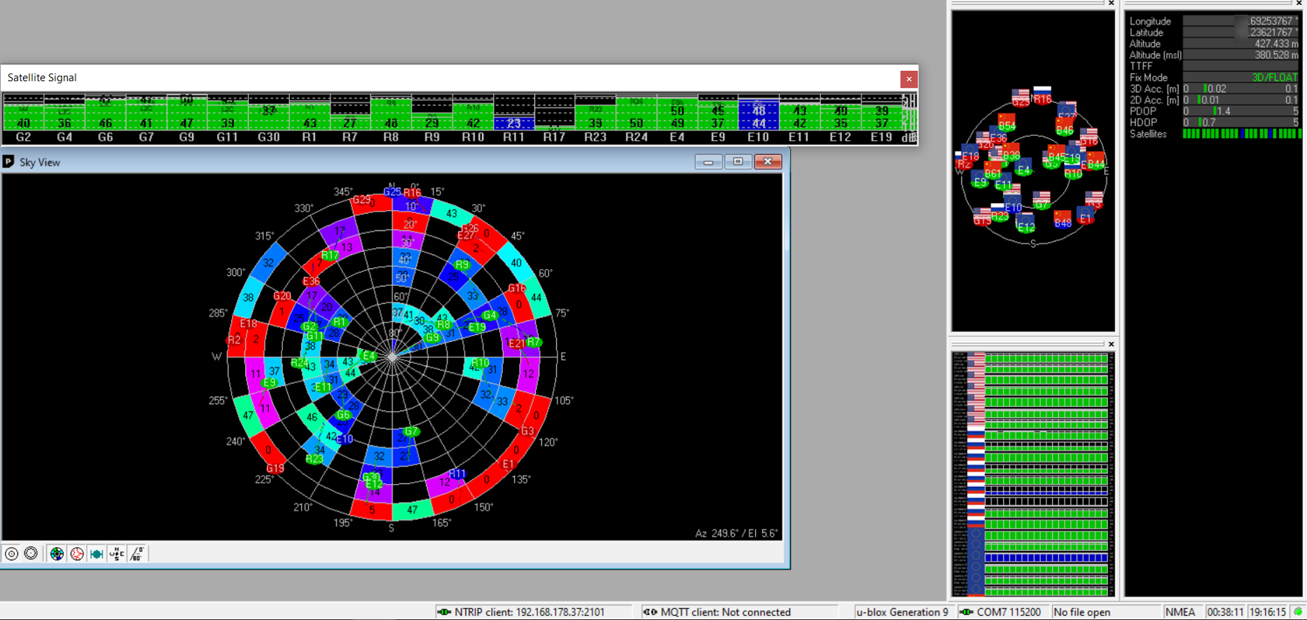
| steel plate 2.tst | >06:00 abort | 3D/FLOAT | X.69253767 | 5X.23621767 | 427,43 | 0,02 | 0,01 | 1,4 | 0,7 | |
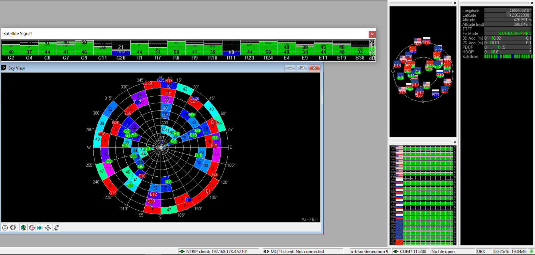
| small box outside | 01:30 | 3D/DGNSS/FIXED | X.69253560 | 5X.23622070 | 426,87 | 0,02 | 0,01 | 1,7 | 0,8 | |
| small box outs.2. | 00:59 | 3D/FIXED | X.69253517 | 5X.23622067 | 426,89 | 0,02 | 0,01 | 1,4 | 0,6 | |
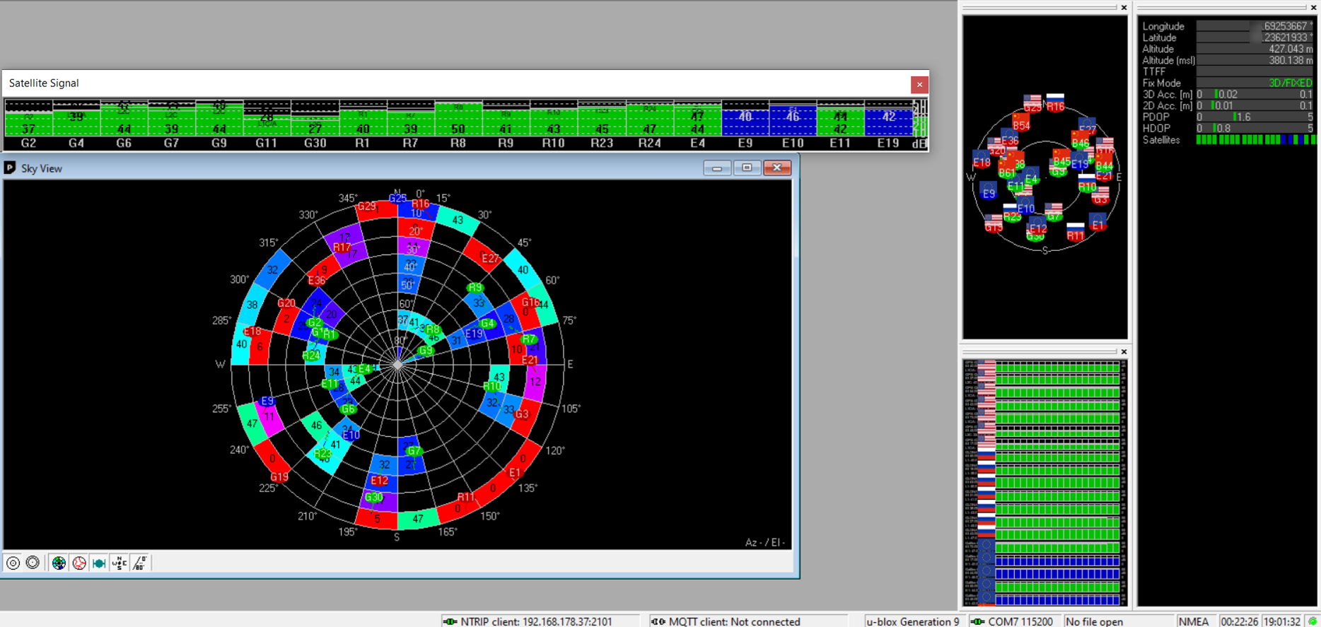
| small box inside | 01:14 | 3D/FIXED | X.69253667 | 5X.23621933 | 427,04 | 0,02 | 0,01 | 1,6 | 0,8 | |
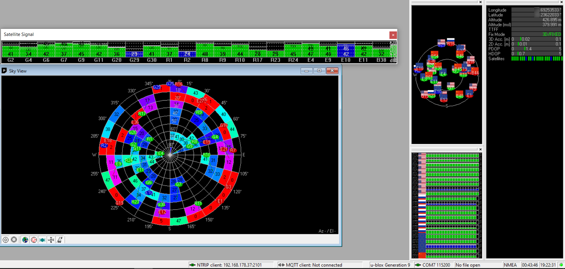
| small box in 2. | 04:07 | 3D/FIXED | X.69253533 | 5X.23622033 | 426,89 | 0,02 | 0,01 | 1,4 | 0,7 | |
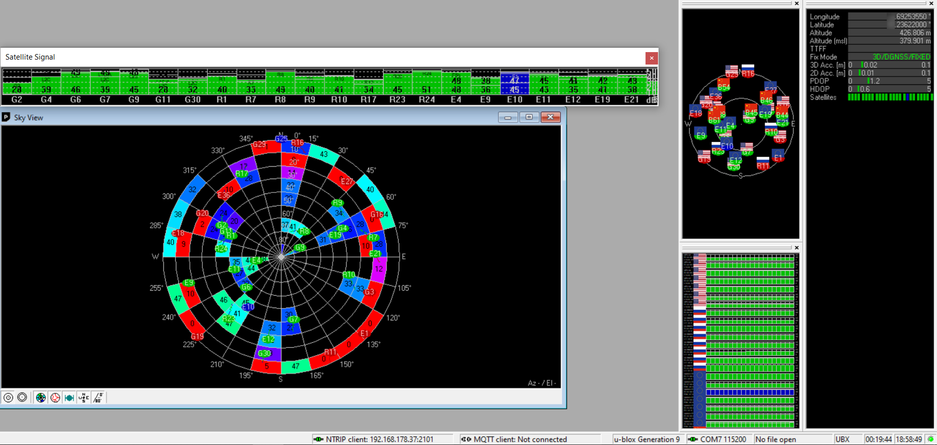
| large box inside | 01:20 | 3D/DGNSS/FIXED | X.69253510 | 5X.23622030 | 426,95 | 0,02 | 0,01 | 1,5 | 0,8 | |
| large box outside | 03:10 | 3D/DGNSS/FIXED | X.69253550 | 5X.23622000 | 426,81 | 0,02 | 0,01 | 1,2 | 0,6 | |
| standalone | 04:54 | 3D/DGNSS/FIXED | X.69253500 | 5X.23622150 | 426,75 | 0,02 | 0,01 | 1,3 | 0,6 | |
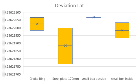
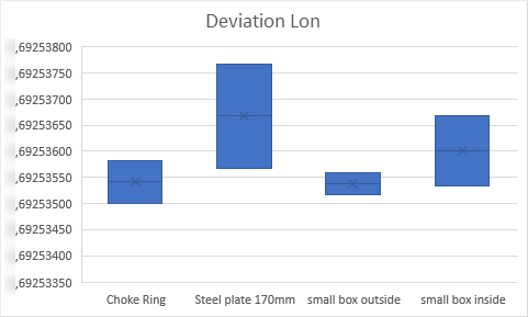
Difference in Lat/Lon of each test
During the test, I noticed that there is not only a difference in altitude but also in lat and lon. I’m not sure if this is normal or if this will cause issues. I wil observe this closely and will check base station again, if it operates in correct state (TIME). Small box outside has the smallest deviation in Lat and Lon. 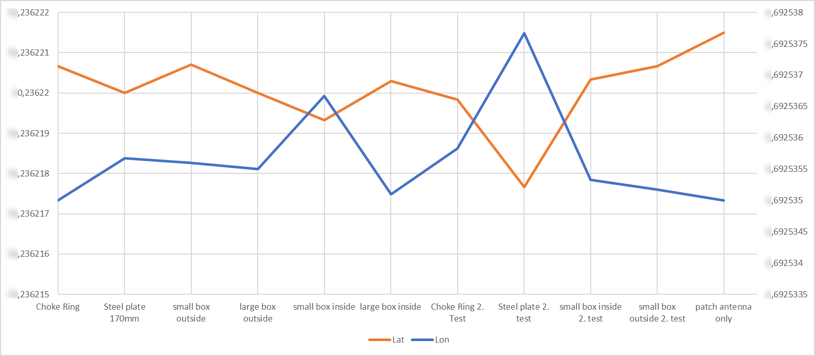
Steel disc
 I did the test two times
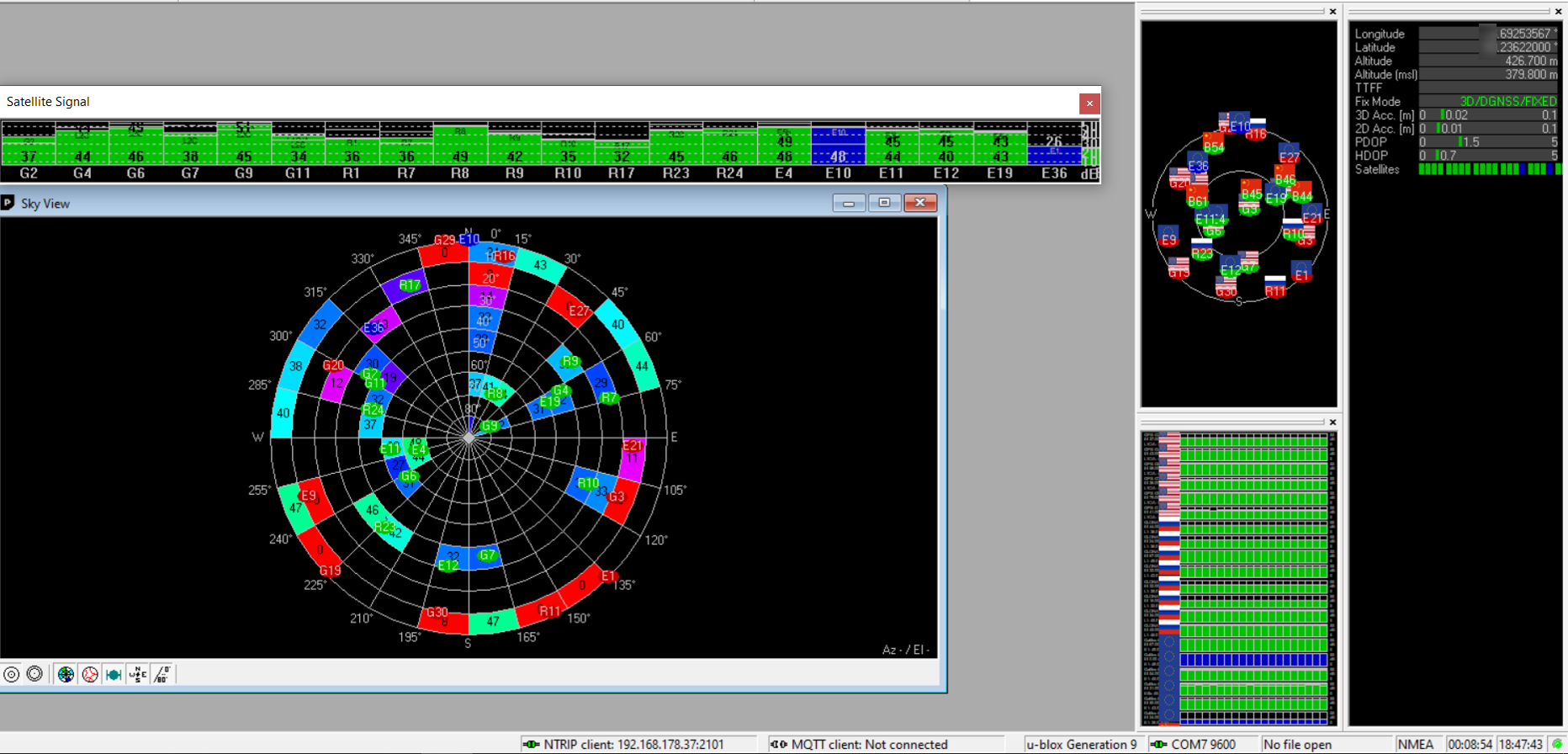
Small box inside
For this test, I placed the antenna inside the small box. The box acts as some kind of choke ring with only one ring. 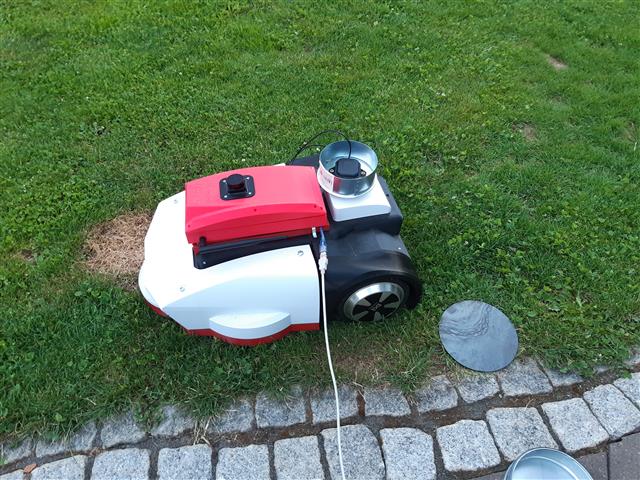
Small box outside
For this test, I turned the box and placed the antenna on top of it like this 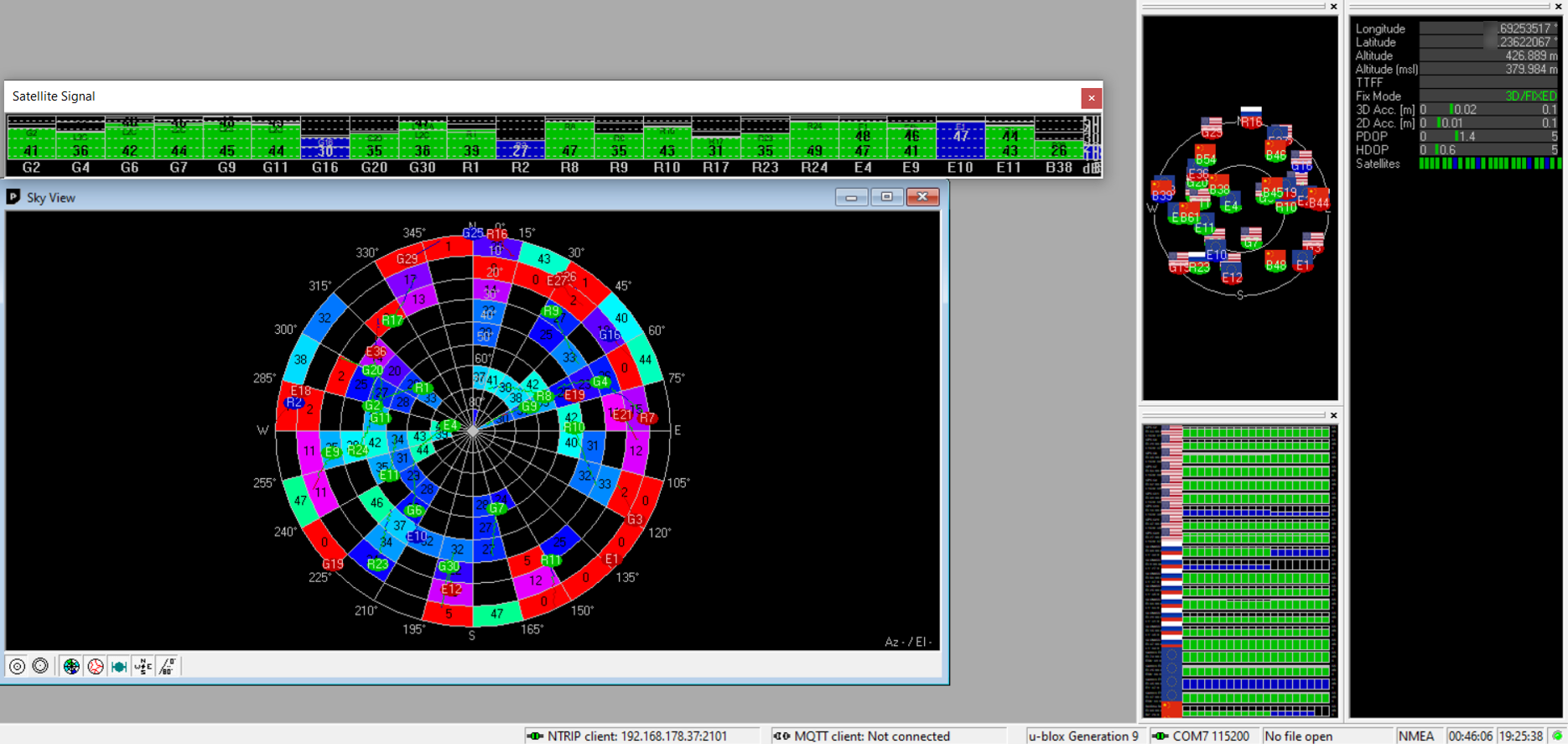
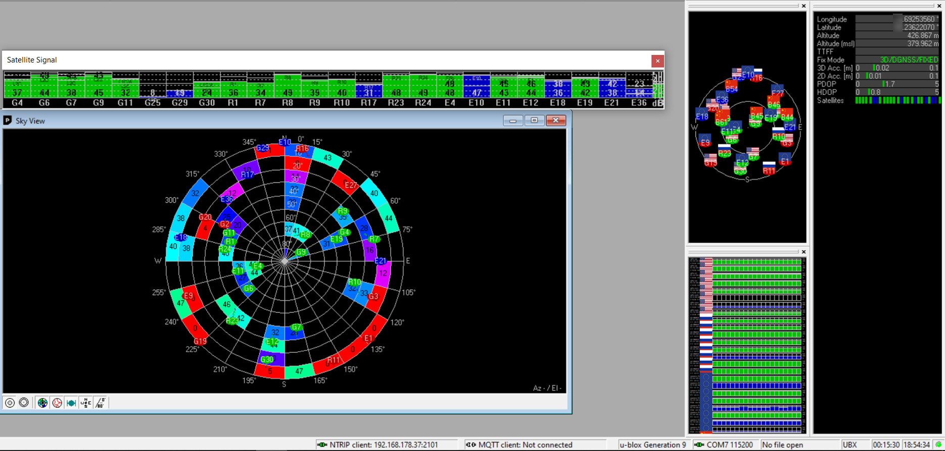
Large box inside
Large box outside
Choke ring
Poor man choke ring antenna. Small box inside the large box, antenna inside small box 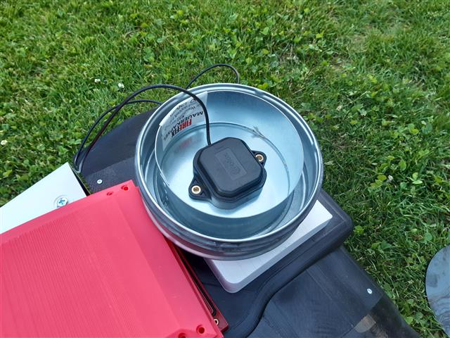
Standalone
Antenna without any ground plane