Emergency swtich and other control units
Each autonomuous robot (and even each other kind of machine) should be equipped with emergency switches. This is also true for HoverMower and therefore, you can equip it with a kill switch. It is up to you, how to do the wiring of emergency switch. Some people will use it to disconnect entire robot from battery. Others, like me, will use it only to disconnect motors meaning the MCUs (like RaspberryPI) will continue to operate but the robot itself will be in a safe condition.
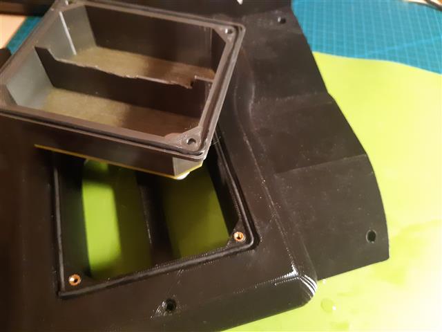
Also Hovermower can be equipped with a main switch (which disconnects battery completely), a button to start the robot, a button for other actions, charging contact and an OLED display to show some status messages. All these control units are placed in a single printed part on the back of the robot. Buttons, OLED etc. are covered with a lid, which snaps to the control unit with magnets. Only emergency switch will not be covered so it can be reached in any situation safetly.
The control unit consists of three printed parts which are:
- inner control unit box
- control unit plate
- control unit lid
You may also need
- magnets for lid
- kill switch
- different kind of buttons (main button taken from Hoverboard)
- charge connector (taken from Hoverboard)
- 0.96” OLED display
- sponge rubber cord 2mm OD
Two Cable Gland M12 are used to route all necessary cables between Motor body upper and inner control unit box. To keep water out, place some sponge rubber cord into the groove of Motor body upper and into the groove of inner control box.