Front section
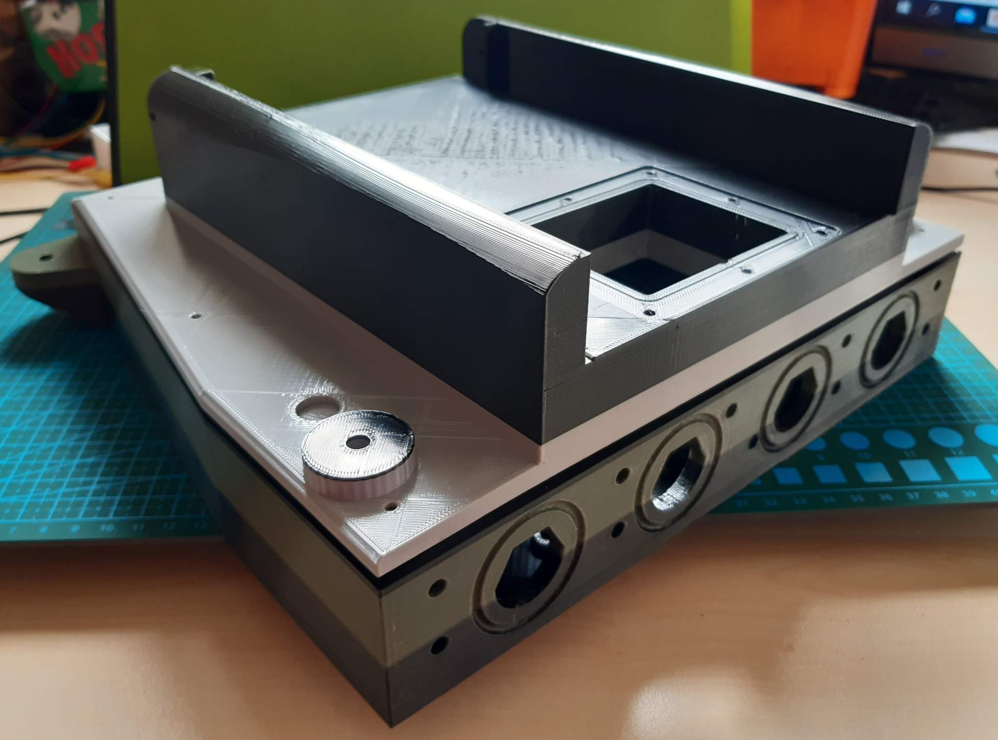
The front section consists of two parts only. These parts will be the housing of mow motors and maybe additional electronics. 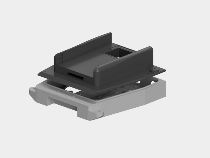
Therefore, lots of holes for knurled brass nuts M3 are available. Again, please insert them only into holes you need. There is no reason to place a nut into each single hole. On top of Mow_lower, you find eight holes for, again knurled brass nuts M3. You must equip them as they are used to mount Mow_upper and Mow_lower together. 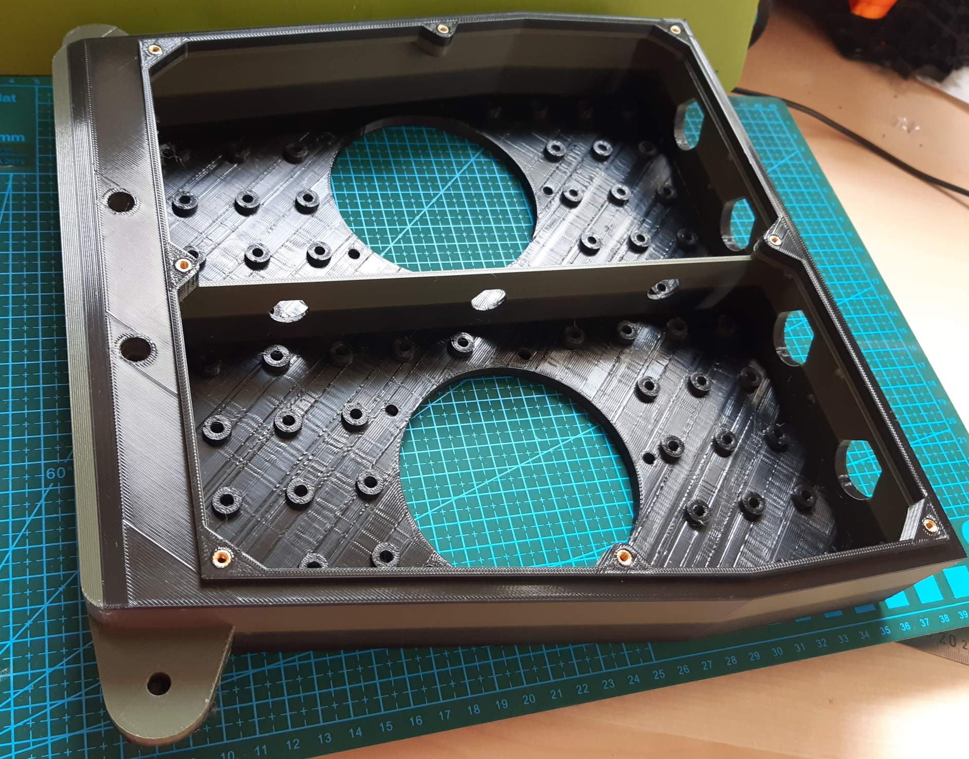
To route cables between front section and PCB Box, a large cutout has been designed in Mow_upper. As the PCB Box is detachable, plugs like D-SUB connectors are used here, which are mounted to a separate cover. It also provide a groove to seal this cover. Add eight knurled brass nuts M3 into Mow_upper. These will secure the cover and also your plugable connectors. 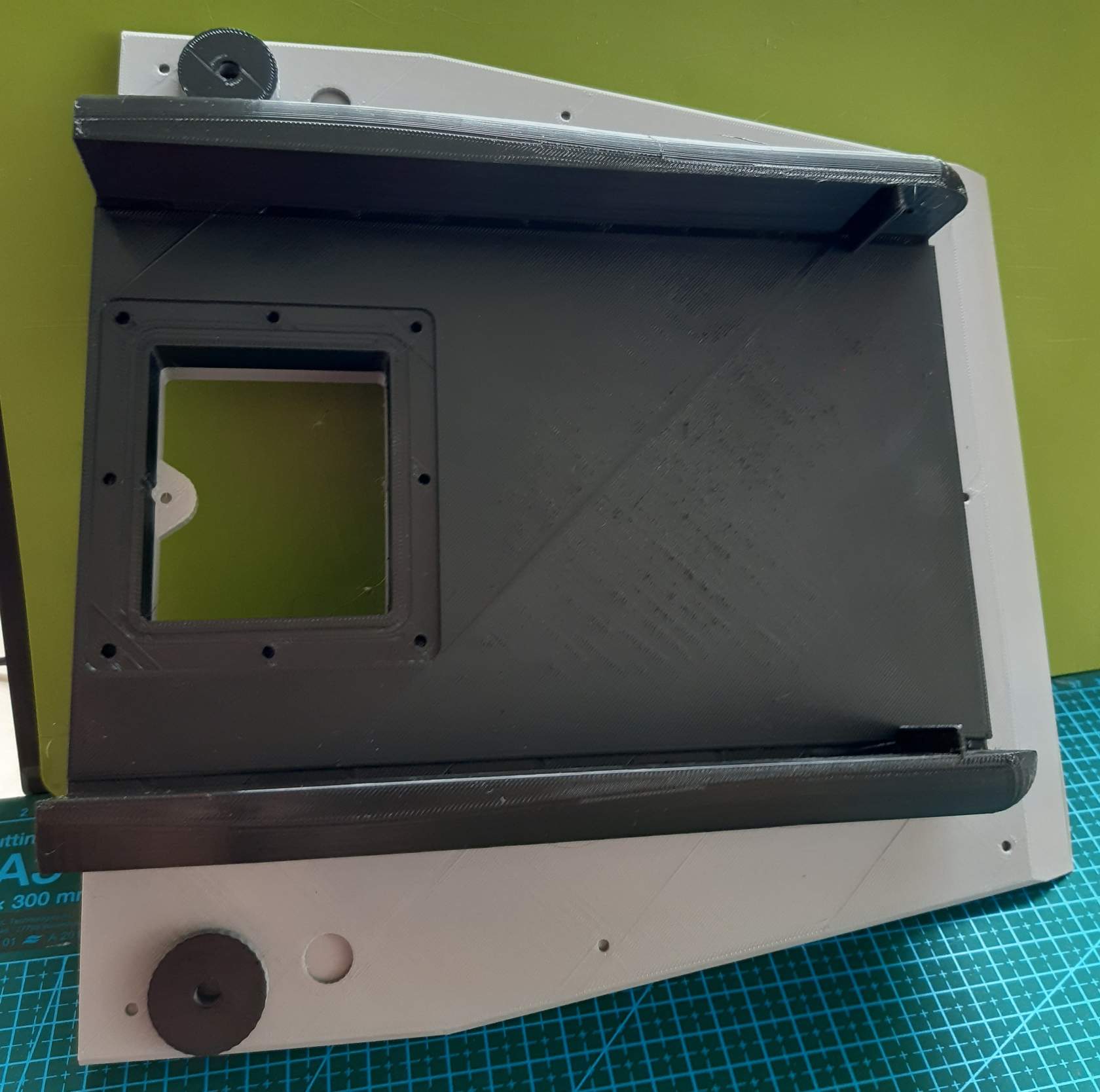
Bumper switches
Hovermower uses the front chassis (white) to detect collisions with obstacles. Therefore, two micro switches (roller style) needs to be assembled to part “Mow upper”. First, solder some cables to the micro switches. They should act as NC (normally closed). This way you ensure also to detect failed wirings. To keep the switches in place, glue two M3 washers (double stacked) on each mounting hole, on each side of each switch. This means, you need 16 washers in total for the two switches (2 switches x 2 holes per switch x 2 washers per hole x 2 sides) 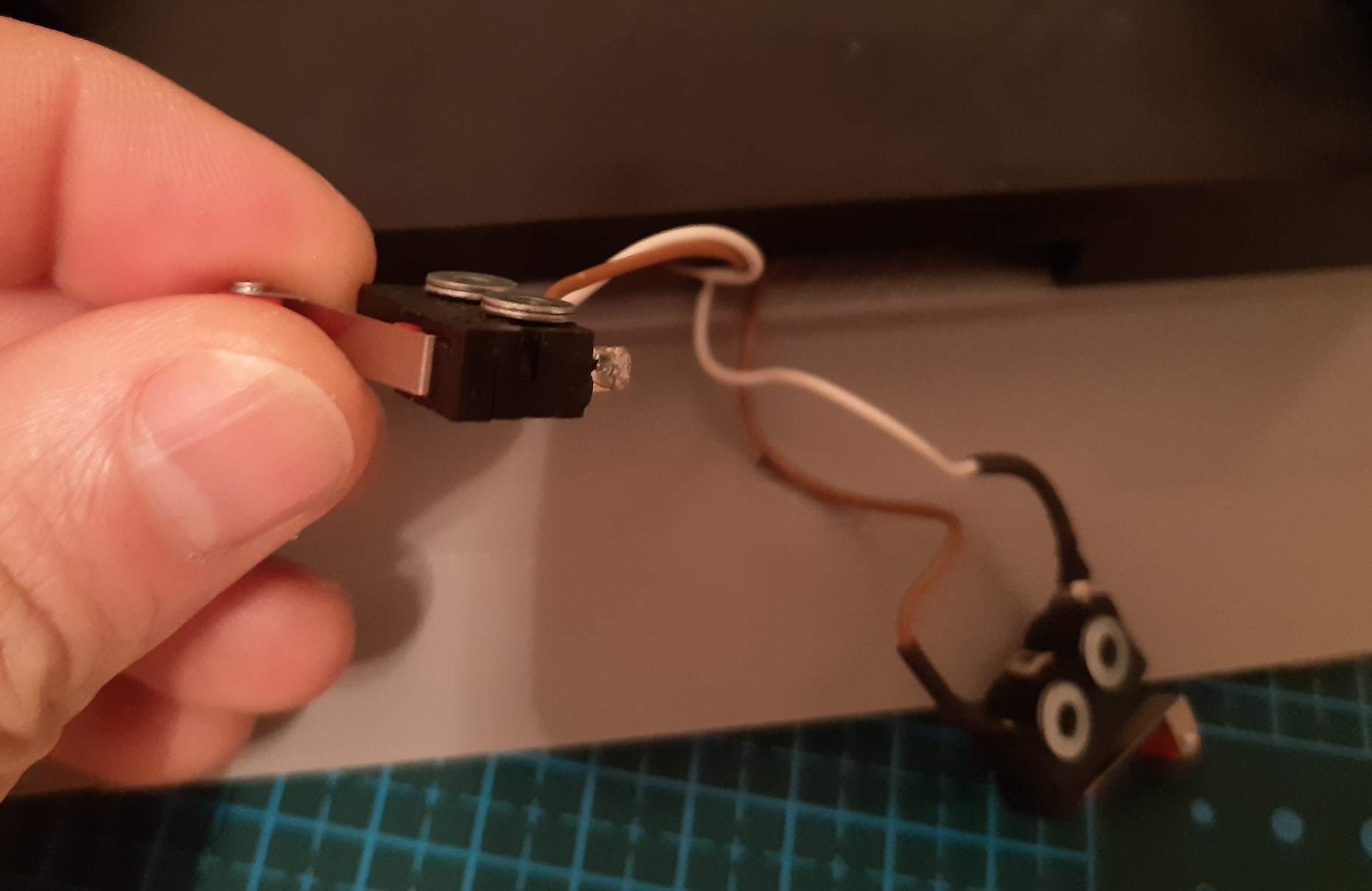 Next, route the cables through the small hole on each side of the cutout, which acts as housing for switches. After all steps are done, use some silicone or hot glue to close the holes and prevent water from entering.
 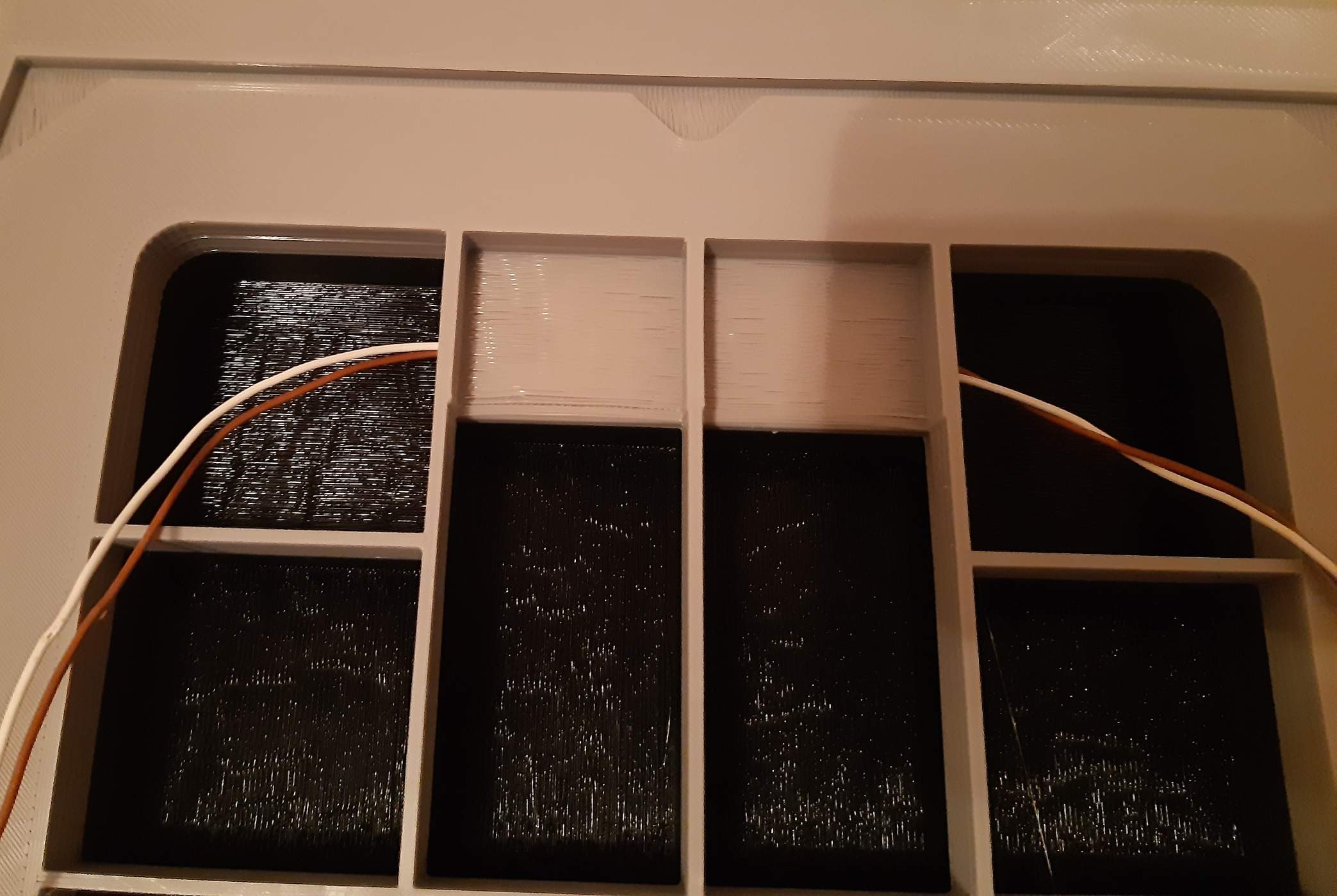 .
.
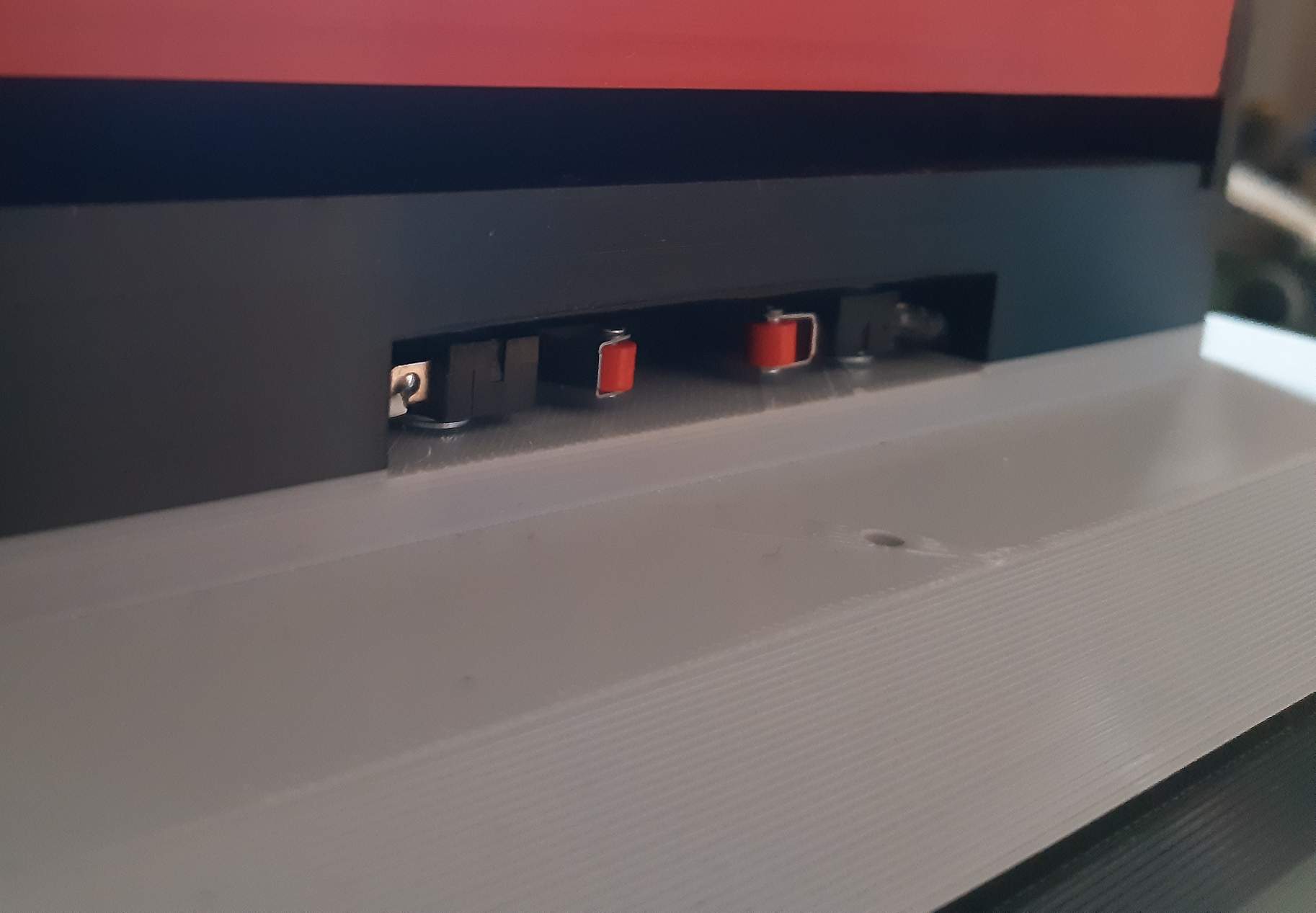
Place the switches as shown in the picture below. The roller should oriented to the front. Use 4x M2x20 screws and screw them from the inner side (the side shown in picture above) through the switches.